Interesting facts (FAQ)
Basic principles and some interesting details about WITT products.
Please choose the product category for your question:
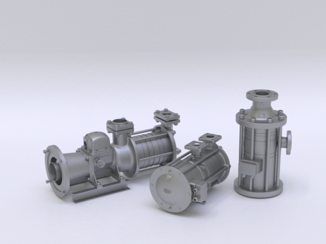
Refrigerant pumps
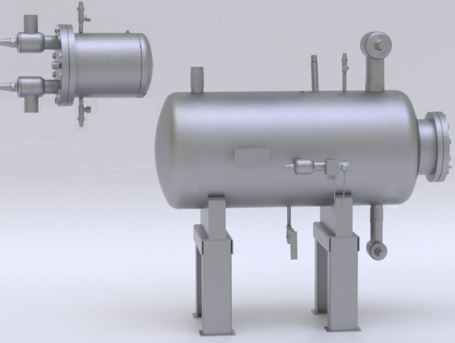
Expansion technology
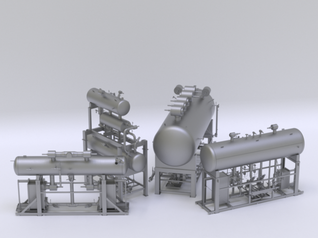
Separation technology, receiver and units
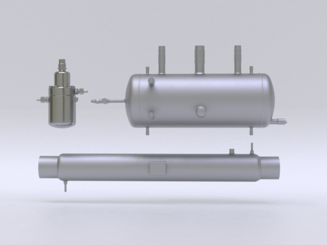
Oil management
Refrigerant pumps
HRP - hermetic refrigerant pump
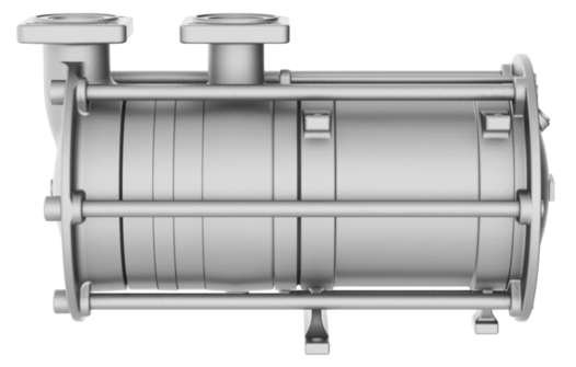
What should be considered during installing the HRP refrigerant pump to prevent cavitation?
Rapidly varying load conditions of the compressor cause the refrigerant to boil in the separator and gas components to be observed in the refrigerant on the suction side of the HRP refrigerant pump. These conditions increase the risk of cavitation!
It is therefore important to ensure a sufficient diameter of the suction piping and at least an suction height of one meter when installing the HRP.
Due to the open design of the impellers, the HRP is able to deliver a reduced volume flow, even with increased proportions of gas in the refrigerant.
What refrigerant pump capacity actually reaches the consumption points?
Our HRP - hermetic refrigerant pump is always selected taking into account the pressure losses in the piping down to the consumers. This means for you, your requested operating point is actually served with the pump we offer.
All lost volume flows are already taken into account in the design.
How long can the HRP refrigerant pump run without liquid refrigerant?
The HRP refrigerant pumps are more sensitive to dry running due to the canned motor than a GP refrigerant pump.
Both, the engine and the bearings require liquid refrigerant for cooling and lubrication. In order to minimize wear on the pump, the HRP must therefore not run without refrigerant and must be protected by an INT engine protection.
Additional differential pressure monitoring and a differential pressure-dependent overflow valve as well as a minimum level switch at the separator are recommended.
How should the HRP refrigerant pump capacity diagrams be interpreted?
The performance curves of our refrigerant pumps are net curves. That means, the performances shown are also pumped by the respective pump into the system.
In comparison to many other refrigerant pumps, the illustrated volumen flows are also 100% available to consumers.
Can the HRP refrigerant pump be operated with a frequency converter and what should be considered?
The permissible frequency range is at least 40 Hz and a maximum of 60 Hz.
If more than one refrigerant pump is operating simultaneously at one separator, the speed must be the same for all refrigerant pumps.
For the check valve to open behind the pump, a short start-up time or steep start ramp of 1 to 2 seconds is necessary. In CO2 systems with minimum flow line before the check valve, the start ramp can be increased to 10 seconds to allow a soft start.
GP - refrigerant pump
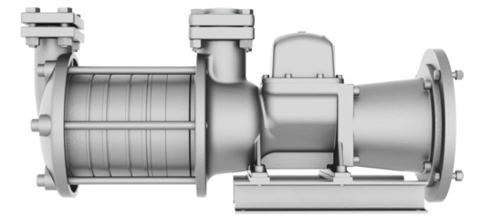
What should be considered during installing the GP refrigerant pump to prevent cavitation?
Rapidly varying load conditions of the compressor cause the refrigerant to boil in the separator and gas components to be observed in the refrigerant on the suction side of the GP refrigerant pump. These conditions increase the risk of cavitation!
It is therefore important to ensure a sufficient diameter of the suction piping and at least an suction height of one meter when installing the GP.
Due to the open design of the impellers, the GP is able to deliver a reduced volume flow, even with increased proportions of gas in the refrigerant.
How long can the GP refrigerant pump run without liquid refrigerant?
The impellers of GP refrigerant pump have very good dry-running properties, but these are very limited as with all refrigerant pumps.
On the other hand, the shaft seals are more affected by dry running, so a dry run should definitely be prevented / minimized.
In order to minimize the wear of the pump, the GP must be secured via a degassing line to the separator and a vortex breaker in the separator.
An additional differential pressure monitoring as well as a minimum level switch at the separator is recommended.
What is the recommended operating engine speed for the GP refrigerant pump?
The GP refrigerant pump can be operated at min. 960 1/min up to max. 1740 1/min.
The use of a frequency converter leads to changed speeds and depends on the motor used.
Which engines can be mounted to the GP refrigerant pump?
The GP refrigerant pump can be used with all standard flange motors. The power of the motors depends on the selected refrigerant.
NRP - refrigerant pump
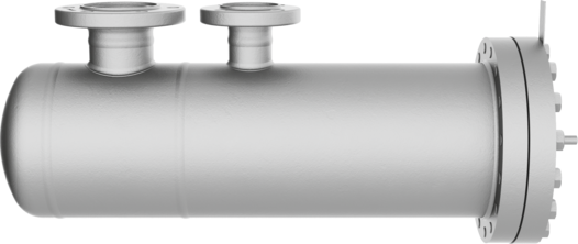
What must be observed when installing the NRP refrigerant pump to avoid cavitation?
Rapidly varying load conditions of the compressor cause the refrigerant in the separator to boil up and gas components in the refrigerant can be observed on the suction side of the NRP refrigerant pump. These conditions increase the risk of cavitation!
It is therefore important to ensure that the suction line has a sufficient diameter and that the inlet height is at least one metre when installing the NRP.
Due to the open design of the impellers, the NRP is still able to deliver a reduced volume flow even with increased gas content in the refrigerant.
What capacity of the refrigerant pump actually reaches the consumers?
The NRP refrigerant pump is always selected in such a way that the pressure losses in the pipework to the consumers are considered.
For you, this means that your requested operating point is actually served by the pump we offer. All loss flows are already considered in the design.
How long can the NRP refrigerant pump run without liquid refrigerant?
An internal dry-running test was carried out: The laboratory test was carried out over 12h with an NRP 3/12 without refrigerant, without connection to a refrigeration system (air was pumped). The subsequent test showed no signs of wear on the pump.
How should the NRP refrigerant pump performance diagrams be interpreted?
The capacity curves of our refrigerant pumps are net curves, i.e. the capacities shown are also pumped into the system by the respective pump.
In contrast to many other refrigerant pumps, the volume flows shown are also available to consumers from 0 % to 100 %. A major advantage of the NRP is that it can run the entire performance curve and does not require a Qmin and Qmax orifice.
Can the NRP refrigerant pump be operated with a frequency converter and what must be observed?
The permissible frequency range is a minimum of 20 Hz and a maximum of 60 Hz.
If more than one refrigerant pump is in operation on a separator at the same time, the speed must be the same for all refrigerant pumps.
A short start-up time or steep start ramp of 1 to 2 seconds is required so that the non-return valve behind the pump can open. Constant pressure control is possible with the WITT NRP, as the pump is intrinsically safe via a motor cooling line. Thanks to the constant pump pressure, the consumers can be optimally supplied with refrigerant. This ensures an increase in system efficiency.
Pressure losses with 2-phase flow CO2
Due to the higher density of CO2 gas, significantly higher-pressure losses are to be expected compared to NH3. This must therefore be considered when designing the pipework (low velocities) and pump (higher differential pressure).
Expansion technology
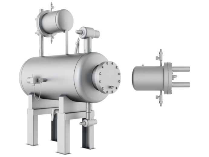
Why is it advisable to install a separate high-pressure float regulator per outlet when installing a condenser?
When installing the HR or HS on the condenser, one float controller per output should be provided per condenser.
If a high-pressure float regulator is used for several condenser outputs or even for several condenser, these outputs must have equal pressure losses and sufficient static height must be present in the supply line to the float regulator.
In general, it is more cost effective to use a smaller highside float regulator per condenser outlet than a few large highside float regulators with elaborate piping and installation.
A highside float regulator can also be used up to max. 3 m above (or up to 30 m away) from the condenser.
What is the pressure in the highside float regulator?
The highside float regulator always has the highside or condensation pressure.
A highside float regulator relieves all condensed refrigerant via a throttle directly to the low-pressure side of the system.
Why is it possible to install a highside float regulator above the condenser outlet?
Through a vacuum nozzle, the pressure in the highside float regulator is minimally lowered, whereby the condensed liquid refrigerant is sucked into the highside float regulator due to the pressure difference.


